
Process Designer
Functionality
The service name in the microservices orchestration environment is qbpmdesigner. Example Swagger link: http://qbpmdesigner.****namespace full name****/qbpmdesigner/swagger-ui/#/
The business process designer module provides the following functions:
- Create, delete, copy, edit groups of processes at different levels of the hierarchy.
- Create a process group template based on an existing group.
- Switch to the process template interface
- Display cards - a list of process groups and their creation.
- Go to the template list view for the process group, which displays summary information about the templates.
- Create a process from a template in the process group cards interface.
- Switch to the process template view and edit it (for users with the role "QBPM Administrator" or "Verifier").
- Create, edit, view diagrams.
- Copy, delete, archive diagram versions.
- Save a version of the diagram as a template.
- Go to the diagram version editor interface
- View detailed information about process pools and steps in version view mode.
- Interact with the diagram mini-map.
- View a list of diagram versions and compare them.
- Export the diagram to a .bpmn file.
- Save the diagram as an image.
- Switch to edit mode to design the process
- Design a business process using BPMN notation elements and custom elements.
- Check the diagram for errors.
- Publish.
- Import a diagram.
- Set the color for a process step.
- Side panel "Properties" for configuring a process step.
Process Designer Interface
List of Process Groups
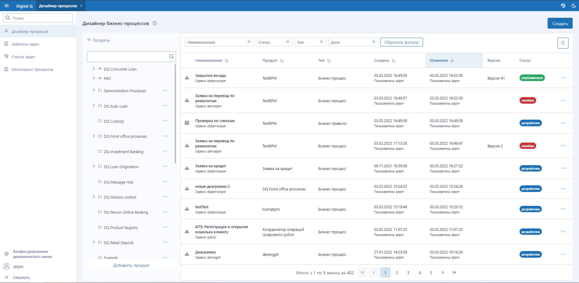
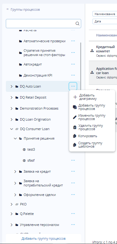
In the business process designer interface, the list of process groups is available in the left side menu. Process groups can be nested at any level, usually up to a maximum of 3-4 levels. Available actions for process groups:
- Add/remove/modify/copy process groups.
- Add a diagram to a process group.
- Create a template process group.
- Add/expand service - for products from Q.Archer.
List of Diagrams and Their Versions
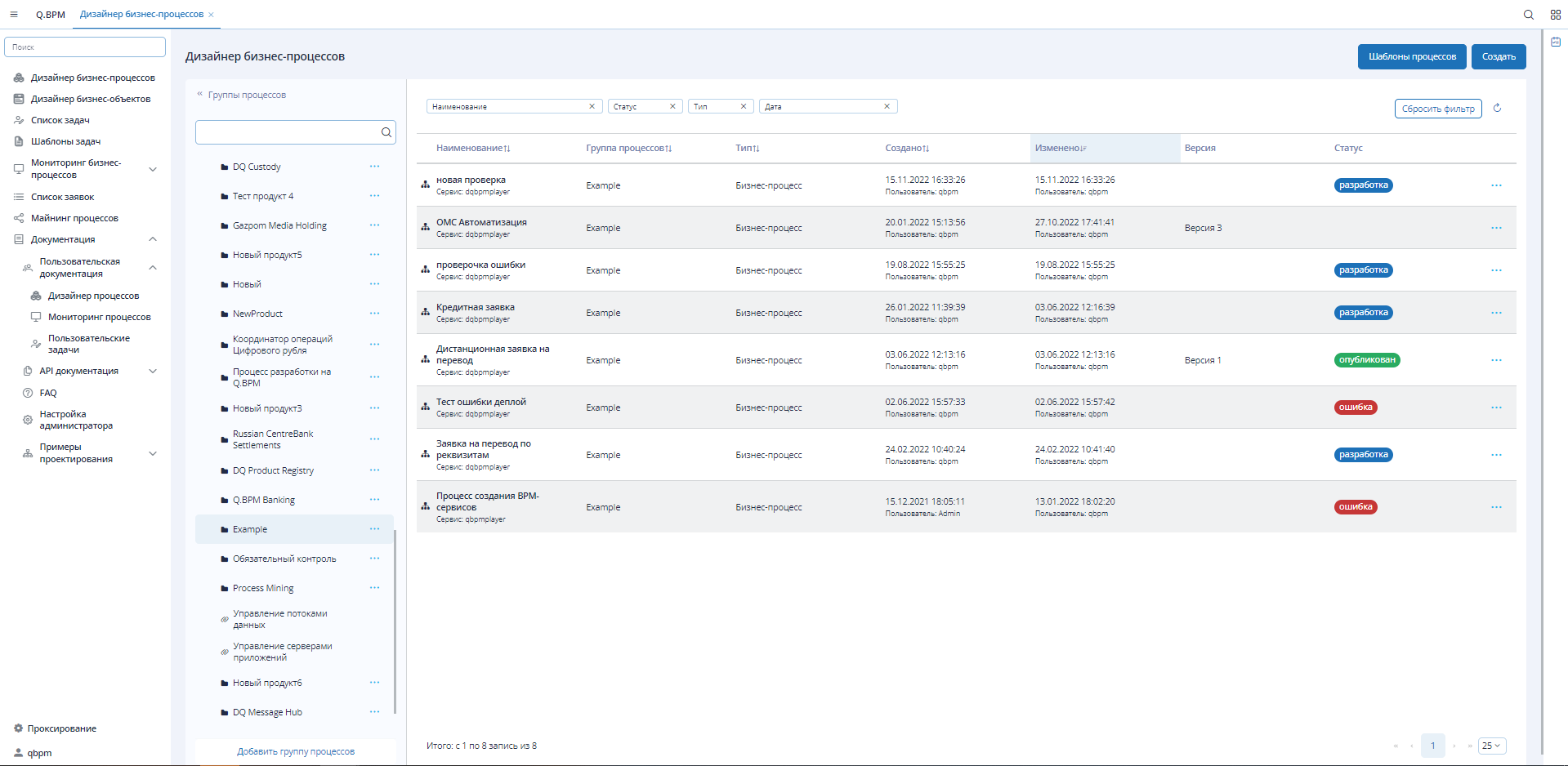
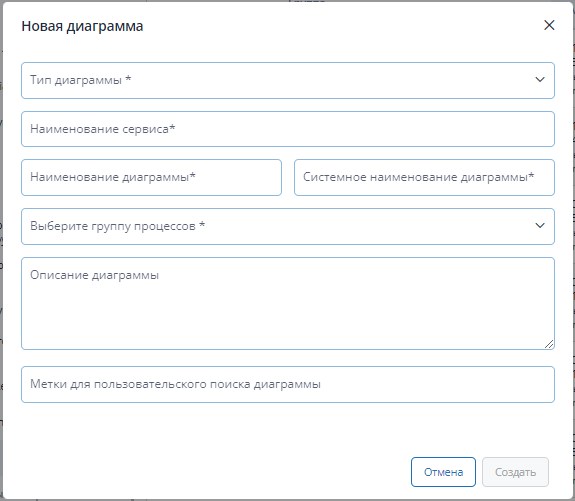
The list of diagrams is presented in tabular form on the form. The list supports filtering: diagram name, diagram version status, type (BPMN - process, DMN - rule), creation date. By default, all diagrams are displayed in the list. When selecting a process group, the diagrams of the selected group are displayed. Each diagram supports versioning. Each version has one of the possible statuses: published, development, publication error, archiving error, archive. When creating a diagram, the first version is always created. Additional information is also specified when creating:
- Belonging to a product.
- Diagram type.
- Name and system name.
- Service name - a service created based on qbpmplayer that will publish the version of the diagram.
Process Templates
Process templates provide users with the option to choose an already implemented (template) process for their purposes. This allows users not to design a business process from scratch but to use a partially or fully prepared solution, substituting their parameters into the process steps.
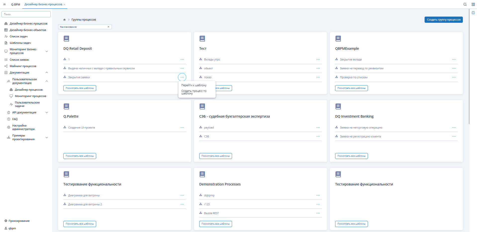
The interface of diagram templates displays information in the same way as the main process designer interface. A list of process groups in the form of cards is available. Each card pre-displays 3 diagram templates. For a diagram template, the "Ellipsis" button provides options: go to the diagram view form, go to the form to create a process from the template. Clicking "View all templates" transitions to the diagram template list form, also in the form of cards. The template card includes: diagram image, template status, description. In the diagram template editor, the view mode is available. The edit mode is only available to users with the "BPM Administrator" or "Verifier" role.
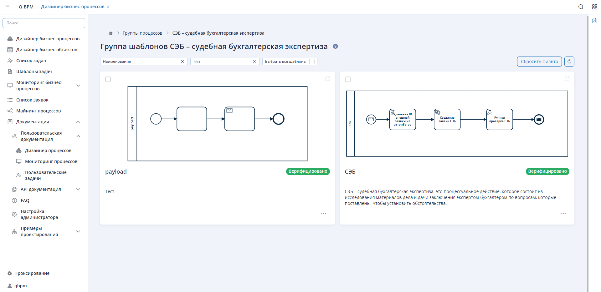
Templates with the status "Under verification" can be viewed, but processes cannot be created based on them until they are verified.
Diagram Editor
The diagram editor interface allows you to design a business process or decision tree depending on the type of created diagram. The editor allows designing different types of diagrams using BPMN 2.0 and DMN notation elements. The editor form supports two modes: view and edit. In edit mode, the "Properties" side panel is available on the right to configure process pools and process or rule steps.
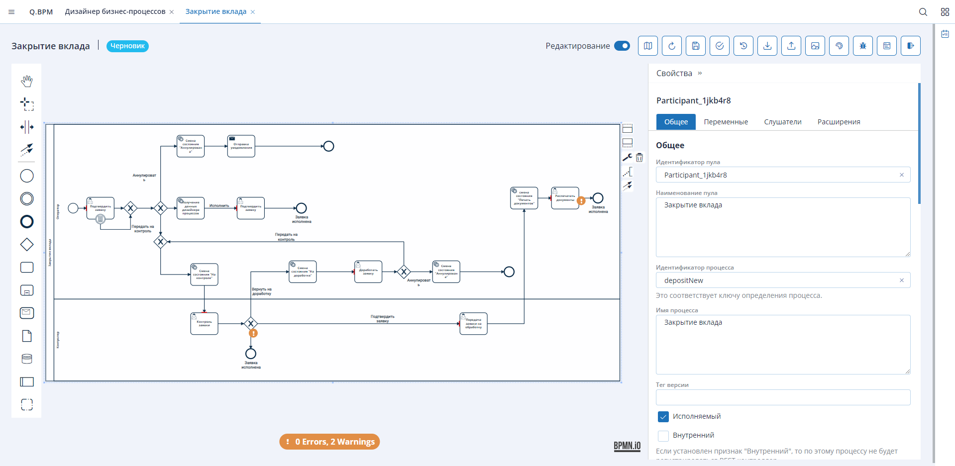
In the upper right corner of the editor, important functionality for interacting with the diagram is located (buttons from left to right):

-
Minimap - toggle on/off. With a large diagram, it makes orientation easier;
-
Refresh - update the diagram version if another user has made changes or if some changes have not been applied;
-
Save (unavailable in view mode) - for manual saving of the diagram. Any change automatically saves the diagram;
-
Publish (unavailable in view mode) - publishing the designed diagram. Packaging the diagram into a microservice and creating a controller accessible in Swagger;
-
Version History - view the list of existing diagram versions and go to the version comparison form;
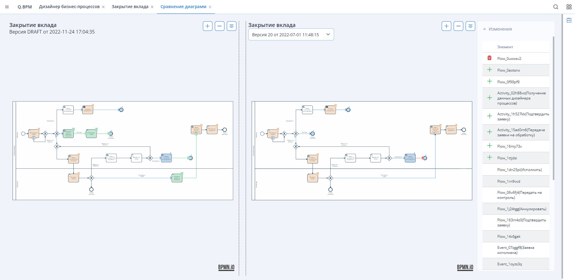
-
Import (unavailable in view mode) - import a previously created BPMN 2.0 notation diagram;
-
Export - export the designed diagram to a file with the ".bpmn" extension;
-
Download Image - download the image of the designed diagram;
-
Element Version (unavailable in view mode) - highlighting process steps with color;
-
Check Diagram - check the diagram for critical and non-critical errors;
-
Save as Template - save the diagram as a template;
-
Close Tab - close the tab with the diagram editor.
Properties Panel
Various settings for diagram objects are made in this panel. For each type of diagram object, unique settings are present in the panel.
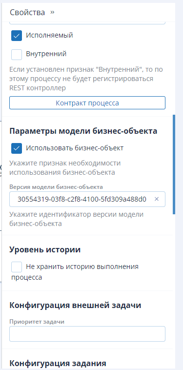
For the process pool and process steps, you can set KPI - execution time metrics. These metrics can be used later in process analytics. In addition to KPI, other functionality is available:
- "Executable/Internal" checkbox - publishing the diagram with the creation and absence of a REST controller;
- "Process Contract" button - a modal window for managing incoming and outgoing parameters of the process pool;
- "Do Not Store Process Execution History" checkbox - when this option is enabled, new controllers will not be created for new process versions. Only one controller will be available.
- "Runnable" checkbox - when enabled, it means the diagram can be published and executed.
Each type of diagram step has its own list of settings in the properties.
Elements for Diagram Design
Business Process
A business process is a single process pool with a beginning and an end, within which a logical sequence of various steps is executed. Using BPMN notation, numerous different steps can be designed within a business process, including calling business rules or other processes. Several business processes (process pools) can be designed within a diagram version. For each process pool, when publishing the diagram version, a controller is created in Swagger.
BPMN notation contains many different types of nodes, with the main element being the task, which comes in various forms. You can learn about BPMN 2.0 notation on the internet or in the Camunda 7 documentation (opens in a new tab). This section will cover the main types of nodes and their configuration.
Decision Tree or Business Rules
The decision tree consists of linked business rules. Any rule in this tree can be invoked in a business process. For the invoked business rule to be executed, all dependent business rules starting from the last node must be executed.
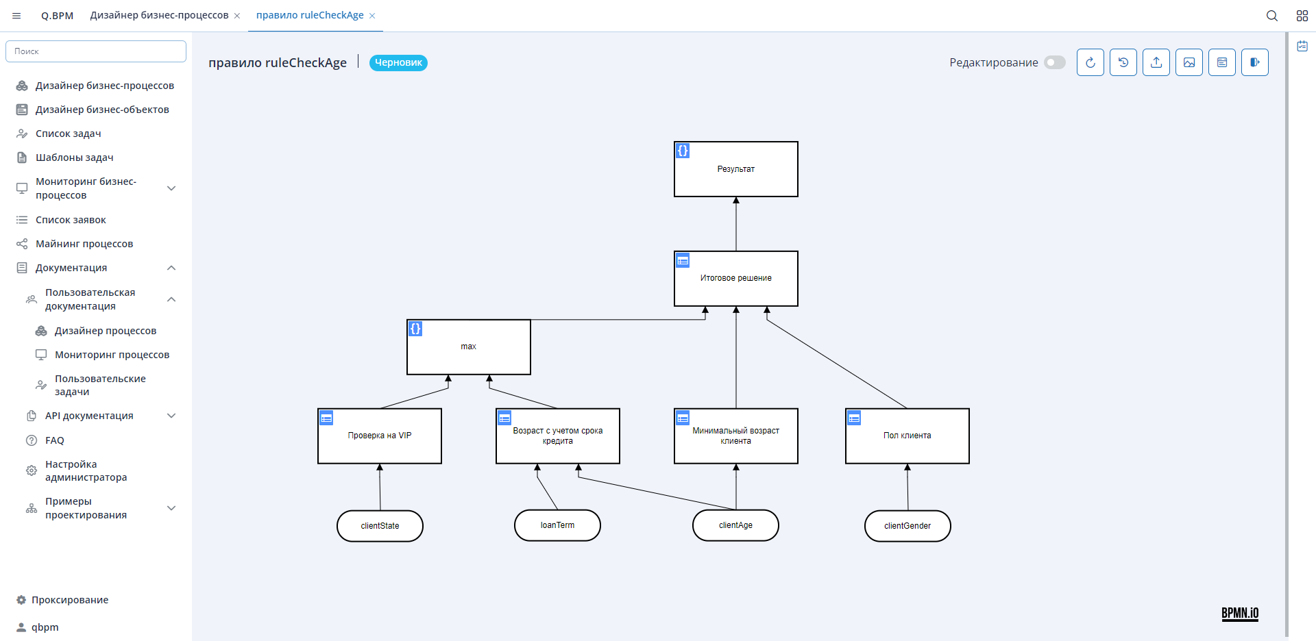
Let's consider the example of the decision tree "ruleCheckAge". A simple scenario: in the business process, you can initialize the "max" rule - in this case, two dependent child rules will be executed first, the computation will take place, and only then "max" will be executed. Alternatively, you can initialize the "Final Decision" rule, and then all its dependencies will be invoked, starting from the lowest rule nodes: VIP check, Age considering loan term -> max, Minimum client age, Client gender.
The decision tree diagram has one main element - "decision", which has two types:

- Literal expression - a DMN notation element where logic can be programmed and/or a data processing function can be described using a scripting language.
Several languages are supported:
- FEEL - expression language used in gateways. Language description in the Camunda documentation (opens in a new tab);
- JUEL - widely used in the process diagram, e.g.,
${content.contains("Camunda")}. It can be used together with FEEL; - JavaScript;
- Groovy;
- Python;
- JRuby;
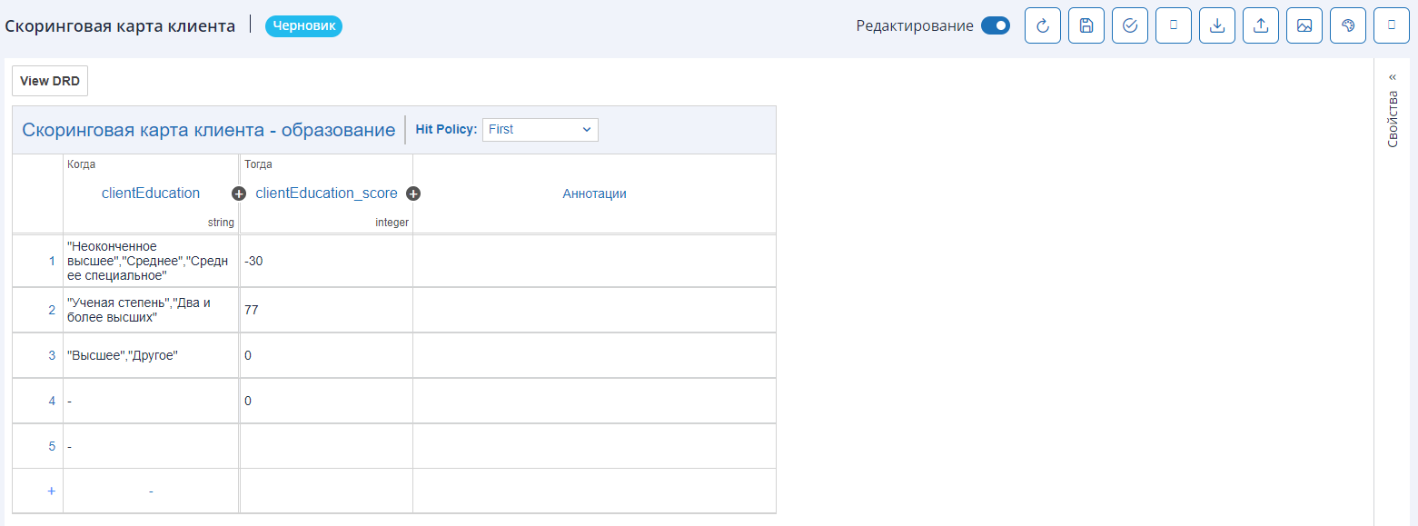
- Table - a DMN notation element in table form. There can be multiple input parameters; the input parameter type is simple, and lists are allowed. Multiple output parameters are also possible, and the output parameter format can have:
- 1 column with one value - resulting in one parameter with a simple type at the output;
- 2+ columns - by default, output parameters are defined in the "map" = key-value list. The required format can be set in the "Task" element in the process diagram. The following solutions are available for the result:
- singleEntry - used when there is one column in the output parameters;
- singleResult - used when 2+ columns are in the output parameters. Used for all rule policies except: unique, first, all collect types;
- collectEntries - used when there is one column in the output parameters, but according to the rule policy, there can be multiple resulting values (rule condition executions);
- resultList - used when 2+ columns are in the output parameters, and according to the rule policy, there can be multiple resulting values (rule condition executions).
Designing BPMN Element to Call a Business Rule
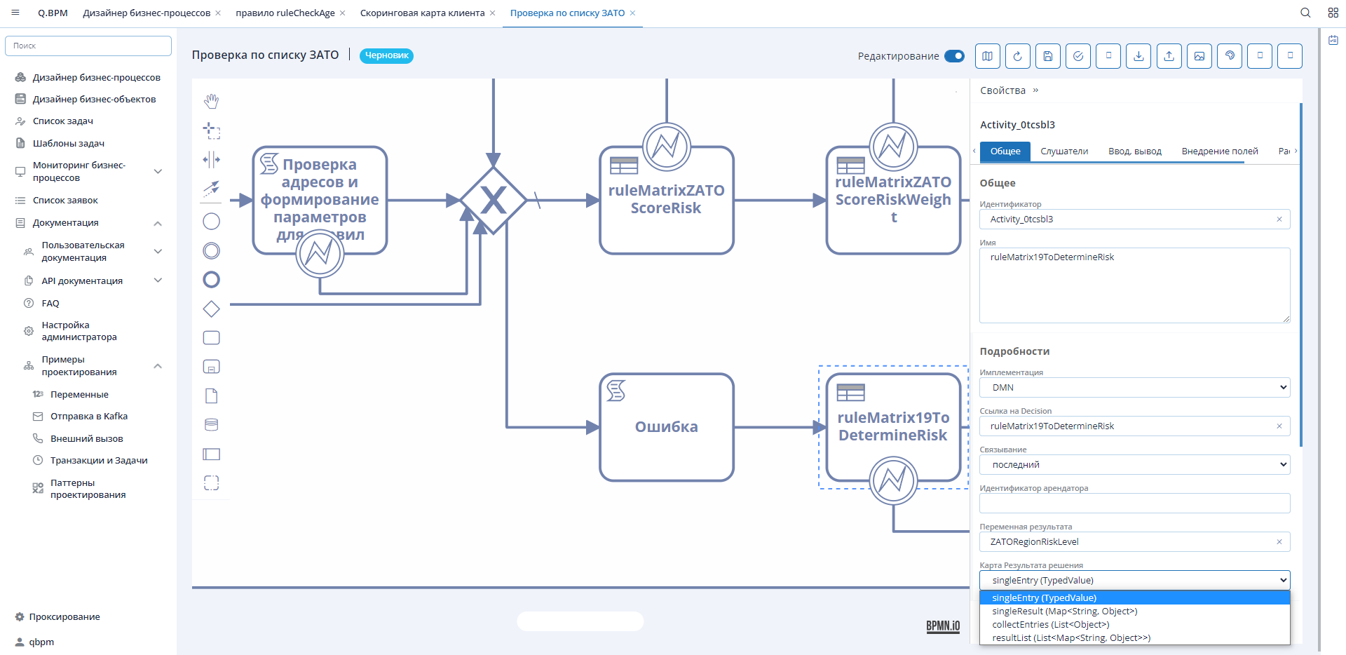
To invoke a business rule during the execution of a business process, it's necessary to design a BPMN diagram element as shown in the example above. To correctly design the element, you'll need to:
- Specify the implementation method - DMN;
- Fill in the "Decision Reference" field - specify the system name of the rule (identifier) from the DMN diagram;
- Specify the linking method - the version of the business rule to be used. You can specify the latest or a version number;
- "Result Variable" - the parameter name in which the result will be written;
- Specify the "Decision Result Map" - output parameter format.
Input parameters are passed to the business rule from the business process context. If as a result of executing the business rule, there are no input variables in the business process context, an error will be triggered, and the transaction will roll back to the last savepoint.
Rule Application Policy / Hit Policy
The policy determines how many decision table rules can be satisfied and which of the satisfied rules are included in the decision result.
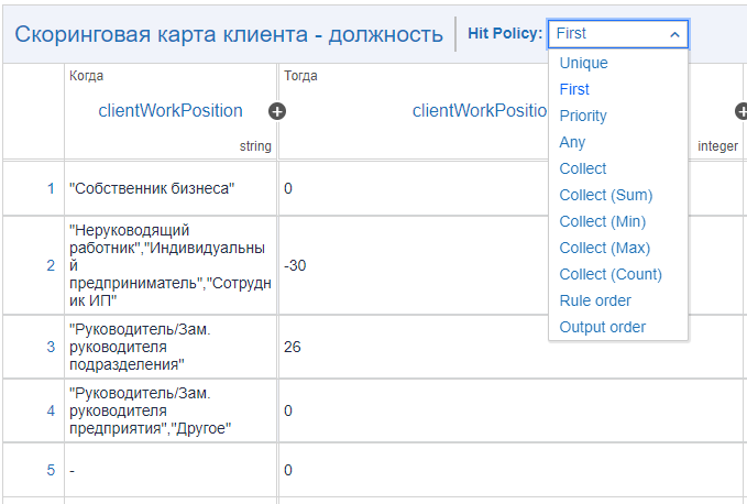
Policies like Unique, Any, and First will always return no more than one satisfied rule. Rule Order and Collect policies can return multiple satisfied rules.
The following policies are supported:
- Unique - can satisfy 0-1 rule. If more than 1 rule is satisfied, the policy is violated;
- Any - can satisfy multiple rules. However, all satisfied rules must generate the same result. If multiple rules are satisfied that generate different output data, the policy is violated;
- First - can satisfy multiple rules. The decision table result contains only the output of the first executed rule;
- Rule order - can satisfy multiple rules. The decision table result contains the output of all satisfied rules in the order of rule appearance in the decision table;
- Collect - can satisfy multiple rules. The decision table result contains the output of all satisfied rules in an arbitrary order as a list. For the collection, an aggregator can be specified. If an aggregator is specified, the result will contain only one output entry, and the aggregator function will be
Examples of Decision Tree Diagrams
Download DMN ruleCheckAge Download DMN Customer Scoring Card